Signed in as:
filler@godaddy.com


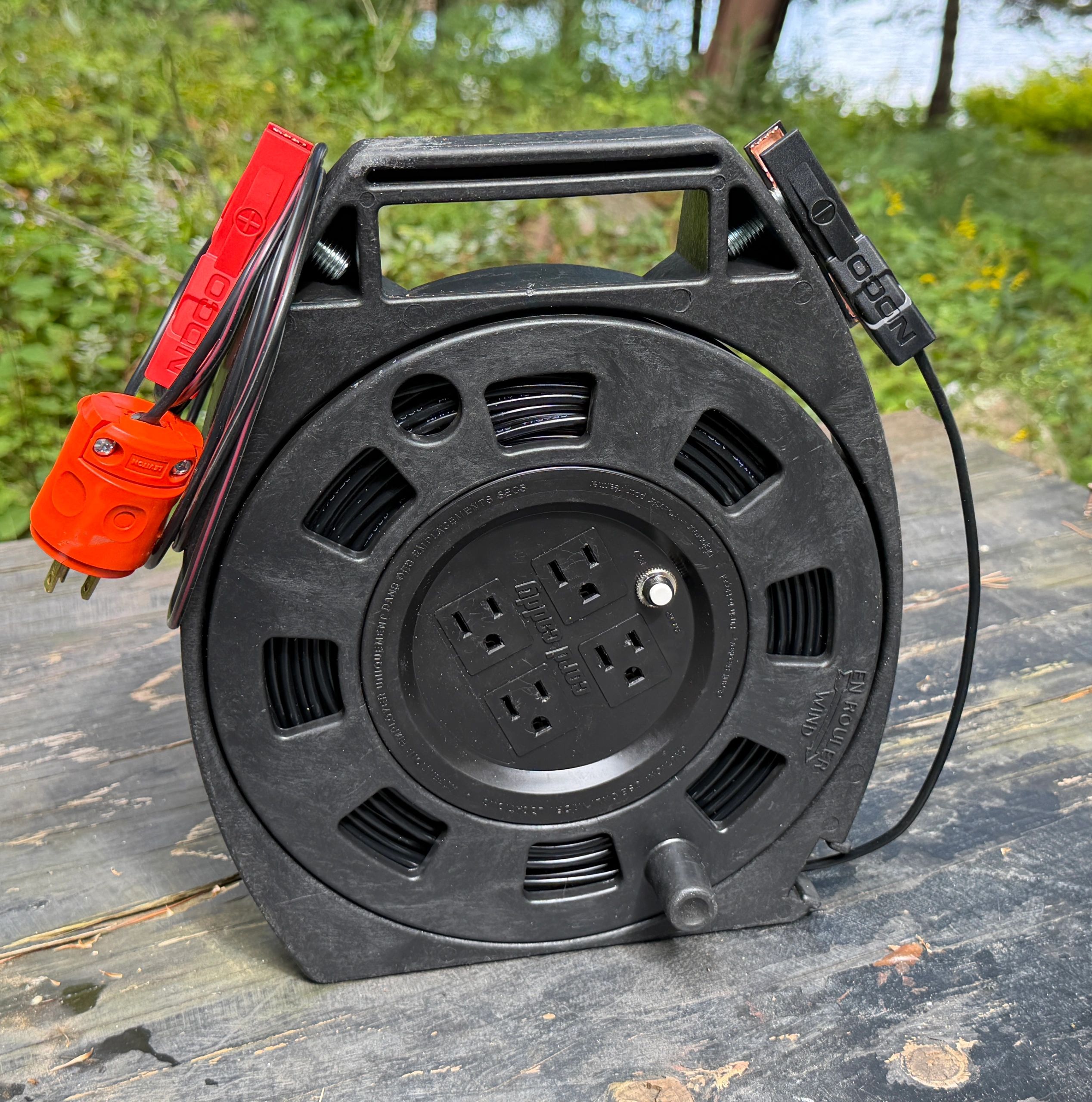
This portable test lead creates the closed circuit required
when using a clamp-on ground-resistance tester between
two grounding points.
WHAT YOU WILL NEED
• Woods Cord Caddy reel — Grainger model 545794
https://www.grainger.ca/en?analytics=nav
• 200 ft of 12-gauge, two-conductor speaker wire
https://www.amazon.ca/dp/B072K6NSWN?ref=ppx_yo2ov_dt_b_fed_asin_title&th=1
• Leviton 515PV-OR grounding plug
https://www.amazon.ca/dp/B007QW7BW0?ref=ppx_yo2ov_dt_b_fed_asin_title&th=1
• NOCO GC017 cigarette-lighter adapter with battery clamps
• 12–10 AWG heat-shrink ring terminals
• Two M12-1.75 × 30 mm bolts
• Solder, heat-shrink tubing and suitable strain-relief material
ASSEMBLY
Separate the speaker wire into individual conductors. Approximately 150 feet of single conductor will fit inside the reel.
Open the rear of the reel and cut the original cable, leaving approximately six or seven inches inside for strain relief.
Identify the ground conductor and solder it to the new 150-foot conductor. Insulate the connection with heat-shrink tubing and safely isolate all unused conductors.
Attach the black alligator clip to the long conductor using a crimped and heat-shrunk ring terminal.
Make a second lead approximately nine feet long. Attach the red alligator clip to one end and connect the other end only to the round ground pin of the orange plug. Add rubber or similar material inside the plug’s strain-relief clamp so it grips the single wire securely.
Drill and tap the sides of the reel for the M12 bolts. These bolts provide convenient storage points for the clips.
IMPORTANT
The orange ground-only plug is inserted only into the modified reel to complete the test loop. Never insert it into an energized receptacle. Verify continuity and confirm there is no connection to either flat blade before using the assembly.
VERY IMPORTANT FINAL NOTE
Once the assembly is complete, clip the red and black clips together and perform a loop-resistance test to determine the resistance of the test lead itself. Record this value; it will likely be approximately 25 ohms. Subtract this amount from every field measurement. For example, if the complete ground-loop test reads 75 ohms and the test lead measures 25 ohms, the actual grounding resistance is approximately 50 ohms.
If you have any questions, feel free to call
John Irwin at 416-931-0785.
Scroll down